Software to automatically visualize gas flow paths through pipingIsolationNavi®
- Infrastructure
- IT & DX
- Maintenance & Management
To resolve these problems, our company worked in tandem with Osaka Gas Co., Ltd., and Daigas G&P Solution Co., Ltd. to digitalize drawings of plant equipment such as piping and control valves (below, “digital drawings”) and developed the IsolationNavi® software which automatically visualizes the flow path of the gas as it changes due to the opening and closing of control valves.
Point
- Changes in the flow path can be automatically displayed with a computer mouse.
- Users can easily create digital work plan drawings.
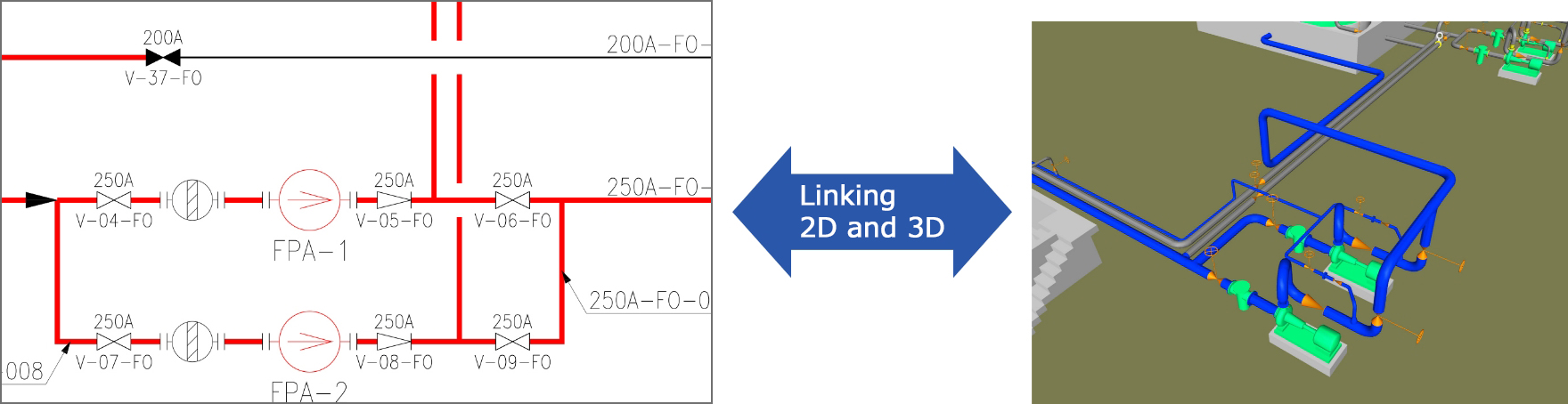
- Users can link digital drawings to existing 3D models of plant equipment.
Outline of IsolationNavi®
Difficulties in isolation work
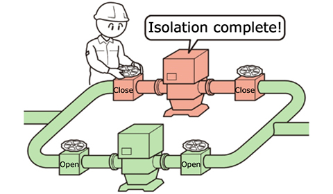
At manufacturing worksites such as gas, power, and chemical plants, regular equipment inspections are performed to ensure safe and stable operations, and repairs are carried out if necessary. During these repairs, it is necessary to safely isolate the equipment targeted for inspection from other equipment currently in operation (below, “isolation work”). Specifically, the valves installed on pipes connecting pieces of equipment must be opened and closed in the correct order to prevent gas leaks and backflows, creating a safe flow path before separating the running equipment from the equipment to be inspected.
Isolation work is separated into planning, which involves inspecting equipment and piping diagrams while drawing up the operating procedure beforehand, and on-site work, where the equipment is manipulated according to the procedure. As the flow path changes upon the opening or closing of a single control valve, the procedure is separated into multiple steps during the traditional planning process, with drawings necessary for the on-site work (below, “work plan drawings”) created by hand and with the aid of schematic software.
In cases where the operations spanned a wide area, multiple drawings would need to be checked, which took up a lot of time. As simulations could not be carried out prior to the on-site work, time would be needed to confirm the operating procedure. Additionally, know-how from the worksite would be necessary for things that could not be understood from the drawings, such as the locations of control valves, making the work unsuitable for junior and inexperienced employees.
IsolationNavi® has the following capabilities.
1:Can be controlled with a computer mouse to automatically display changes in the flow path and range as a result of the opening and closing of valves on screen
2:Allows users to easily create work plan drawings by displaying and saving the open/close status of control valves and the flow paths and ranges for various procedures
3:Allows users to link digital drawings to existing 3D models of plant equipment. Thus, it can be used to enhance understanding of the worksite status and as a training tool to assist passing down know-how.
*Autodesk’s Navisworks Simulate is needed to enable linking to 3D models.
By utilizing IsolationNavi®, whose features are outlined above, workers can create the drawings they need and understand the status of the worksite while confirming changes in the flow path as a result of equipment manipulation. This increases efficiency and enables work sophistication.
Functions of IsolationNavi®
Makes drawing-related work more efficient by simulating flow paths using 2D drawings.
Allows for simulated worksite checks through its 3D linking functionality.
Enables various examinations using attribute information.
It also has the following three functions to enhance its work optimization features.
1:Allows the user to open and close control valves on screen and automatically displays the path flow
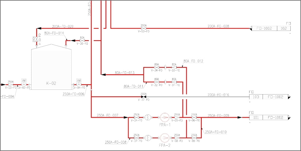
2:Interlinking several drawings
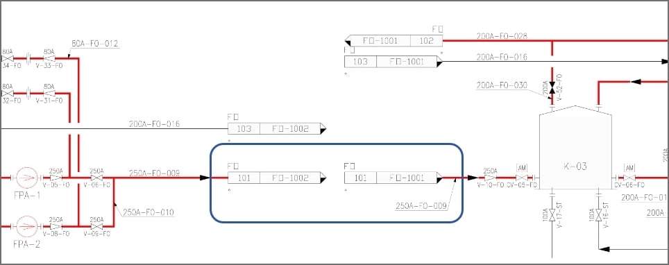
3:Object search (by Tag or No.)
Adding the above functions greatly optimizes work and reduces human errors.